A Beginner’s Guide to Blender’s Wireframe Modifier
One of the coolest features added to Blender since the 2.7 release is the Wireframe Modifier. Keep reading to find out what it does and how to set it up in Cycles and Eevee.
What Is Blender’s Wireframe Modifier?
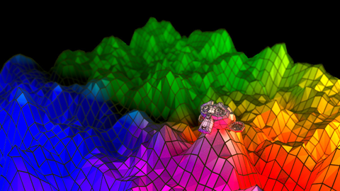
In short, Blender’s wireframe modifier allows you to see what your mesh is actually made of — its topology and contour — which is why a wireframe can come in handy.
It converts a mesh into a wireframe by roaming its surface, assembling all the edges and converting those edges into four-sided polygons. Be aware of the fact that your mesh needs to have a face for it to work. You can define the thickness, material, and other parameters of the frame generated dynamically as well.
To do this:
- Go to the Modifier Properties tab and then click Add modifier.
- In this list, locate Wireframe and select it to activate the modifier and attach it to your object.
- You will now see that the modifier replaces the mesh of your object with a grid pattern.
This grid is based on the actual geometry of your mesh as well as any modifiers that you have running underneath it, which can include the Subdivision surface modifier if you plan to use one.
Wireframe Modifier Tools
The tools you have at your disposal for this modifier are listed below.
Note: When using the Thickness parameter, keep in mind that it’s an algorithmic approximation. While Even Thickness often yields satisfactory results in many cases, skinny faces can cause undesired spikes to protrude from an object. This can be remedied by reducing the angles in the geometry or by turning off Even Thickness.
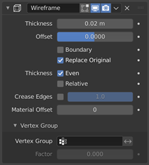
Thickness
Thickness sets the depth or size of the wireframes.
Offset
Offset is a value between (-1 to 1) that changes whether wireframe is generated in or out of the original mesh. Setting Offset to zero will center the frame around the actual edges.
Boundary
Boundary creates wireframes on mesh island borders.
Replace Original
When selecting Replace Original, the actual mesh is replaced with the generated wireframe. If not, a wireframe is placed over it.
Thickness
Even Thickness keeps the wireframe thick by adjusting any sharp corners. This option may improve the quality but at the risk of increasing the calculation time.
Relative Thickness determines the size of the edge and the length of the edge. The longer edge, the thicker the wireframe.
Crease Edges
Crease Edges is used with the partition converter. Enabling this option will cut edges at their meeting points and prevent large curved intersections.
Crease Weight
Crease Weight affects how much crease that meeting points should get.
Material Offset
Material Offset uses the selected material index as the wireframe’s material and is applied as an offset from the first material.
Vertex Group
Vertex Groups restrict the modifier to only selected vertex group. The Invert option flips the vertex group weights, while the Factor option sets the percentage of the vertex that has influence over the final wireframe result.
Rendering a Wireframe over the Mesh
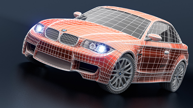
Wireframe modifier over BMW model by Mike Pen
Wireframe modifier over BMW model by Mike Pen
You may find yourself also wanting to display the mesh of the wireframe over the actual base mesh of an object. To do this, uncheck the Replace Original option under the Boundary option. If this was to be rendered as is, what you would see is that the wireframe and the object share the same material.
This can be changed by using the Material Offset option. After making a separate material in the Material Properties tab, return to the Modifier Properties tab and locate Material Offset under the Crease Edges parameter. Changing the index number will designate the material applied to the wireframe.
If you have multiple materials, setting the index number of the Material Offset to anything other than 0 will set the next material in line in the Material Properties to the wireframe. Upon rendering, you would see the object and wireframe have two distinct materials applied to them.
Rendering a wireframe over the mesh can be very useful when posting your work online to showcase your models in a demo reel or portfolio as it shows off the detail of your mesh.
Rendering Wireframes in Eevee
Of course, as with all Blender modifiers, the Wireframe Modifier works in both Cycles and Eevee. The issue lies with procedurally generated meshes or larger objects as Eevee doesn’t recognize Vector Displacement and may slow your real-time viewport renderer to a crawl. So, if you desire to apply the effect on a displaced object, the wireframe will not match the contour of it.
There is an easy workaround for this issue.
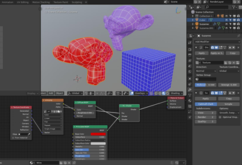
1. Using the UV mapping menu (press U to display) on your object, choose Reset to unwrap the mesh to its shape. When you do, you should see a UV map similar to what is displayed below.
2. Saving this UV as an image, you can take it to the Material Properties tab and make a Material node tree beginning with a Texture Coordinate node that connects to an Image Texture node from the UV to the Vector option.
3. From here, set up a Diffuse BSDF node and connect it to a Mix Shader node.
4. Set your Image Texture to connect to the Diffuse by Color and have its Alpha connect to the factor of the Mix Shader.
5. Take the Diffuse and put it into the Shader option of the Mix Shader and place a Principled BSDF Shader into the other Shader option available in the Mix Shader.
Use the example above to properly set up your node tree. Once complete, you should be able to see the mapped UV texture on your object with Eevee.